Engineers who have been around pre-CAD remember when sketching their designs on paper was a standard part of the engineering development process. They used large drafting tables and a variety of tools to get the angles and edges nice and clean and they did their math on slide rules. CAD pros of today might scoff, but using only these old-school tools, engineers were able to produce the Toyota 2000GT, SR-71 Blackbird, KitchenAid Mixer, and a bunch of other great stuff.
Today, this stage of the engineering development process looks a lot different. Most engineers simply open up our CAD program, start a Spotify playlist, and sketch the design in the program. Then if we need to do some math, we use a calculator or phone.
It may sound strange, but there is actually no fundamental difference between these two approaches. As engineers, we are still creating the same drawings, describing our work with the same math, and we have to make the same considerations for fabrication. Our tools are just different. (Sometimes we even use both tools.)
But whatever tool is being used, if an engineer doesn’t understand how a part works, their drawing is going to be wrong no matter how it was made. Back on the drafting table, they used erasers; today we tap Ctrl+z.
Software Isn’t the Be-All and End-All
Many young engineers mistake understanding how to use CAD software for being skilled in their profession. Admittedly, software is used to save time, provide accurate representations of a design, and improve understanding of the part in a 3D space before it is produced. But it will only ever be a tool in your engineering toolbox, and knowing how to use this one tool is only one aspect of engineering with insight.
The truth is, you can know every facet of the CAD software you’re using, but if you don’t understand what you are doing with it, you may wind up designing a lot of nice-looking scrap metal. So how do we avoid this? To refine this stage of the engineering development process, we must identify what problems need to be solved and what questions we need to ask.
Break It Down
Before doing anything else, it’s necessary for engineers to break a problem down into parts. Once we have determined our sub-problems, then we know what questions to ask to find solutions. Before we even begin designing, we like to break down a problem into the binary. You may call it brainstorming, cooking, or whatever you want, but the crux is this: we’re aiming to make a project less complicated.
Some experienced engineers may have only been involved in a single aspect of a project. Here at SGW Designworks, however, we are often involved from start to finish. For this reason, we need to be able to wrap our heads around each stage of a project, from Phase Zero (pre-development) to design for manufacturing. Due to the complexity of many projects, we believe it’s a good idea to put a problem into sketches and flowcharts — even for the most experienced engineers.
The Drawing Board: Key to the Engineering Development Process
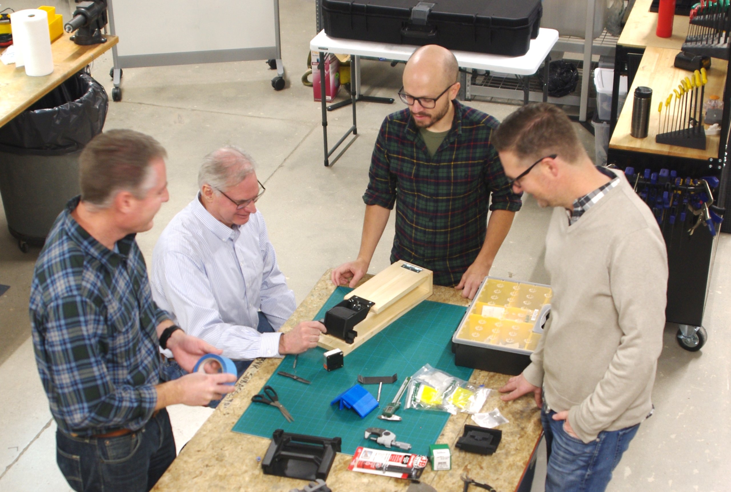
When working in a team, we often use the drawing board to help our teammates understand what we’re talking about. It is also a great way to help explain concepts to clients. Just as software is one tool, there is tremendous value in using hand-drawn, low-tech sketches as another tool to conceptualize ideas.
Engineers don’t need to be artists to take full advantage of the drawing board. (We certainly aren’t!) And our tools of choice aren’t always a literal drawing board, either. Any tactile tool that helps us and our clients understand a problem will work. The drawing board might be:
- A whiteboard
- A pen/pencil and paper
- Legos
- A digital drawing
- Clay
A drawing board can be made out of anything on hand. For instance, if one of our engineers is working a problem and feels compelled to use popsicle sticks to model it, we say do it. Additionally, a paper model can be a handy way to demonstrate a shape.
At SGW Designworks, we frequently use whiteboards to try and develop ideas before they are ever designed in Solidworks. Most people on the team also keep a notebook which can also work as a sketch pad. We try not to limit our thinking to just individual parts, but instead encourage the use of the drawing board to understand entire systems and their subsystems.
Flowcharts — A Great Visualization Tool
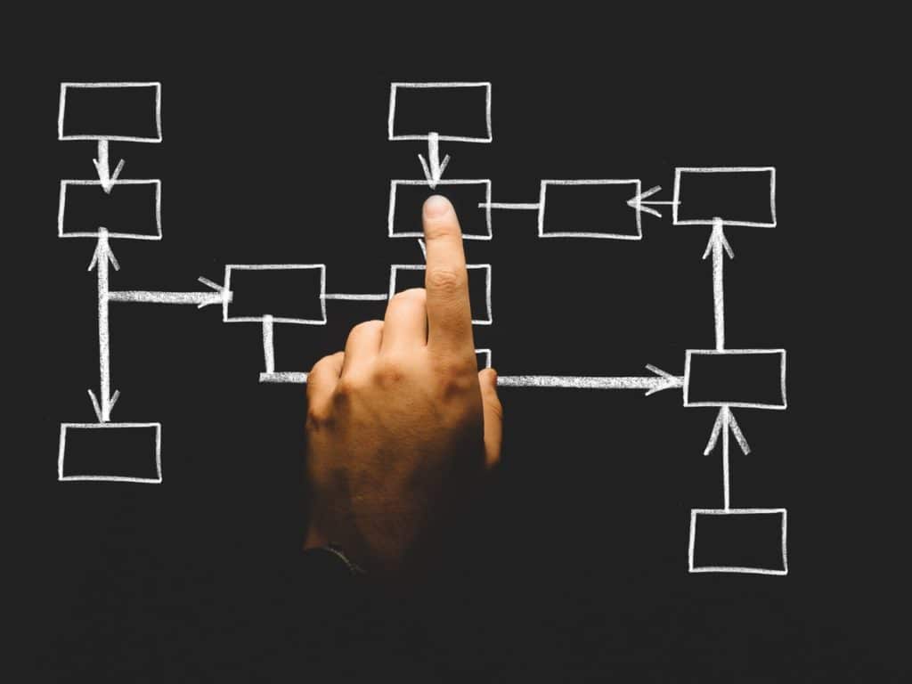
When it comes to entire systems, or for logical progressions sometimes found in software, flowcharts are another great tool. A flowchart is just a series of inputs, decisions, and outputs which are in graphical form. They’re easy to make, easy to change and they help us (and our clients) to easily visualize things.

Think of the flowchart as one way to utilize the drawing board. Where this comes in useful is in illustrating the prioritization of tasks.
Prioritizing Tasks in the Engineering Development Process
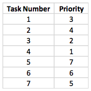
The order tasks appear to come in does not reflect the order they need to be accomplished in order to achieve the desired results. As seen in the heat tile example in our previous blog post, the end result wasn’t necessarily the answer to the biggest problem that needed solving. Similarly, your actual task list on a project may look more like this table.

We find this approach to be most efficient, but when speaking with clients, it’s sometimes difficult for them to understand. Someone who isn’t familiar with engineering processes — and only sees their end goal — may have to be guided.
For instance, a client may want us to build an engine for them, but we may need to build a specialized bracket to be able to even test or use the thing. That’s a real-world prioritization challenge the client may not have considered. And here’s where our drawing board comes in — as a helpful tool for communicating these challenges.
.jpg)


