Taking a product idea from concept to market can feel like a daunting task. Product design companies and product development engineers use a product development process to break down this cycle into manageable steps that pairs the innovation and creativity needed to imagine a product with the process and learning needed to bring that vision to reality.
This process can be hard to visualize when you’re trying to launch your first product. To help show that process, we’ll break down how we helped Christine, a first-time product development client, get her product, an innovative contact lens case, from prototype to production.
Phase 0: Project Definition
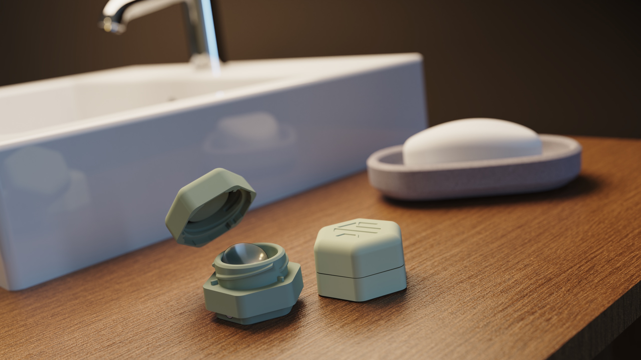
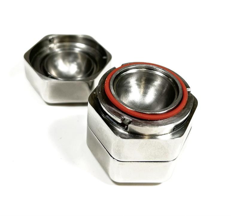
Christine had already spent a significant amount of time on her vision for an innovative new contact lens case designed for travelers before approaching SGW. As a contact lens wearer and pilot herself, she had first hand experience with the frustration of her lens case leaking on flights and her contacts drying out. She also had not found a contact lens case that looked appealing or matched the aesthetics of other travel cosmetic cases or products. Her concept was a stylish hexagon-shaped contact lens case designed for travelers that was 100% leak proof. She came with a stainless-steel prototype she had developed with the aid of another product development agency, but the stainless-steel version was too heavy for travelers and too costly to manufacture. In addition, it had issues sealing and staying tightly secured.
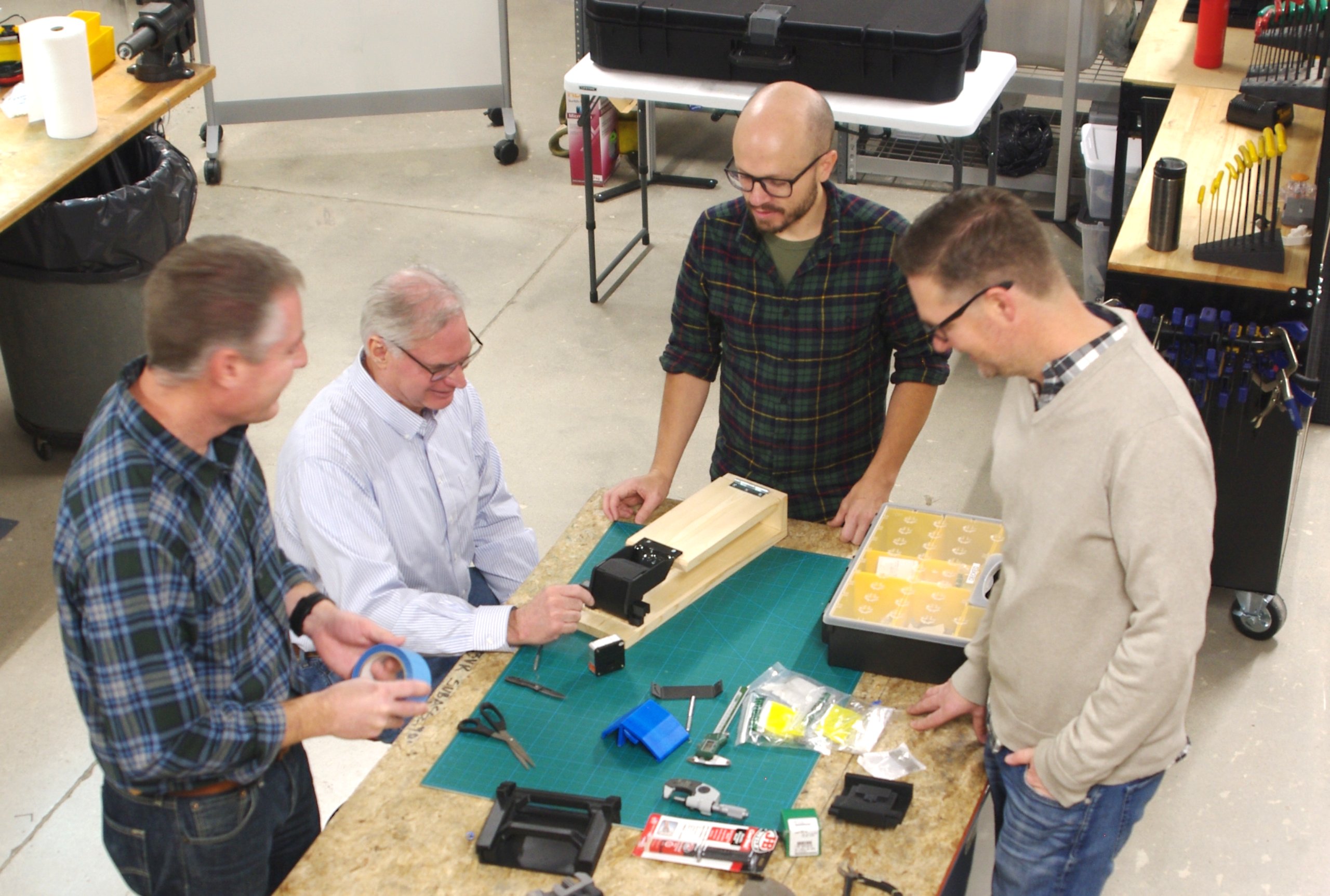
In the definition phase, we had a kickoff meeting with Christine where she brought her current prototype and talked through what she wanted changed and her goals for production and market launch. From there, we did our own internal audit of the prototype and concept. We created a product requirements sheet where we listed the primary features and other nice-to-have features for the product.
The goal of this phase is to define the product requirements, quickly identify major risk items, and spend some time developing pathways to de-risk those items so that we can build a development plan and timeline with an estimated level of difficulty and associated budget. For this project, the biggest risks were converting the design from a machined steel part to an injection molded plastic part – which we knew would involve significantly reducing the material and thickness of the part. The other major risk we identified in our kickoff with Christine was that the product was going to be classified as a class II medical device, so it would need to pass FDA requirements and testing, which we would need to research and build into our design.
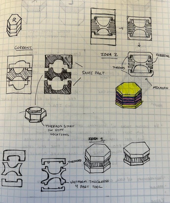
We did a quick design-for-manufacturing brainstorm with a core group of engineers to identify the areas in the current design that would need to change for injection molding. One of the essential aspects of injection molded designs is that parts need to maintain universal wall thickness. The current prototype was a thick piece of material with two cavities on either side which meant we needed to core material out of the middle without interfering with the contact solution cavities or ruining the aesthetics of the product. We threw out ideas for how we could do this, which showed us there were several paths forward and became the basis for the next conceptual phase.
We also spent a few hours looking into the FDA requirements for contact lens cases to get an idea of allowed materials, timeline, and further research that would be needed.
We took this information and built a product development path with an estimated timeline and budget and presented it to Christine. We also presented the small amount of research and early conceptual sketches completed in phase along with assumptions and open risk items that would need further definition as the project progressed. She signed off on the proposed budget, and we moved on to the next phase.
Phase 1: Concept Generation
In this phase, we detailed some of the concepts we had brainstormed in the discovery phase, starting with strategies to eliminate thick spots in the steel prototype while maintaining the hexagon shape. We sketched cross-sections of the product to help visualize these concepts and made quick 3D CAD models to present our concepts to Christine and others.
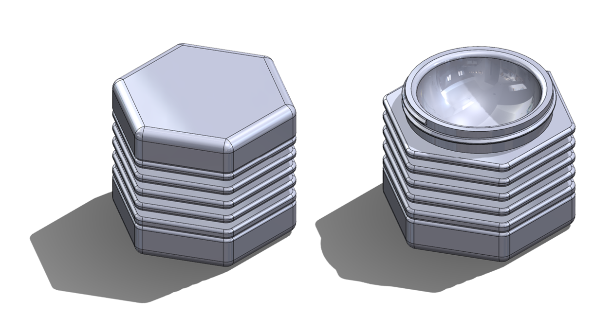

At the same time, an industrial designer on our team evaluated the current prototype. Besides the heavy weight of the product, he pointed out a few other issues he saw from a user experience perspective. Many of the issues were ones that would be fixed in the later phases of product development such as the fit of the lid, the thread type, leaking seals, and gasket retention. One interesting perspective he had was that with the current prototype, users could only access one contact lens at a time, which differed from the user experience than most contact wearers are accustomed to with standard lens cases.
To see if this was a cause for concern, we watched contact lens wearers take their contacts out and put them into traditional cases and noted that many remove both caps, wash their hands, place their solution and contacts into the cavities and then re-attach the caps. With the current prototype design, it took longer to interact with the contact lens case because only the right or left lens could be accessed at a time. For those that cared to wash their hands before removing their contacts, this case also introduced a contamination point or second hand-washing step when needing to flip the product over after already removing one contact.
To some, the additional steps might not seem like a big deal but the added steps when partially blind or groggy in the morning may be cumbersome and to others that care about minimizing the chance of any contamination in their contact solution, the extra touch points in the process may be a dealbreaker. Generally, to get people to adopt a new product it needs to be somehow better than the existing solution while being as easy to use.

This observation led us to concept ways to allow access to both lenses at the same time, which also opened the design to other improvements. We concepted ideas with hinged halves, magnets, various twist on/off ideas, and snap fits between the two halves. Being able to separate the two cavities gave us access to the middle of the parts which allowed for more options to core the thick areas that were constraining us in our earlier injection moldable conceptual designs. Separating the two halves also allowed for different aesthetic and user experience design choices like color choice between the right and left lens cavities and tactile feedback when separating and attaching the two halves

While these features could be potential improvements to the design, they also had downsides for Christine to consider. Separating the halves created more parts which would increase her tooling cost and figuring out how the halves attached would create more mechanical design requirements and take longer to design and perfect. While additional user interfaces and user experience opportunities might increase the appeal of her product, they would also cost more to develop and create more choices for her to make throughout the design process. We presented these tradeoffs to Christine, and she took the time to weigh her options before deciding to invest more into development to improve her product.
Phase 2: Concept Development and Analysis
In the previous phase, we had presented a few different ways to separate the two halves. In this phase, we started to test those concepts with an initial engineering design. The separable halves created new product requirements to consider in the design – mainly that the hexagon shapes needed to align perfectly when the halves were together, the two halves needed to be the same height when separated and lay level on a table, and the caps that stored the contact solution needed to stay secure when separating the two halves. This eliminated a few concepts, like a threaded connection and some friction snap fit designs.
The concept Christine gravitated to the most was magnetic halves that snapped together with a satisfying click. We spent some time creating a 3D CAD model of this idea, calculating the magnet size and clearances between parts, and working through how to assemble the parts together.
We also focused on important details from her original ask like making this design leakproof and improving the security of the caps. Her original prototype had three bosses sticking out on the inside of the cap that fit into ramps on the main cavity body to twist the cap on and an O-ring that sandwiched between the two parts to provide the seal for the contact solution. The issue with this design choice was that the boss/ramp feature didn’t have a clear locking mechanism so that parts could unlock unintentionally, and the O-ring didn’t have a strong enough retention feature, so it frequently fell off the product or became misplaced which interfered with sealing and taking off the caps.
We changed this design in a few ways, the most important change was moving from a boss and ramp twist design to bottle threads with a locking position at the bottom of the threads. The bottle threads themselves form a seal, but we also kept the O-ring as part of the design – moving it to a more secure position within the cap.
Independently, Chistine was working with an attorney to patent her product idea and with an FDA testing consultant agency to ensure the final product would pass regulatory requirements. In addition to our own research, information from these two groups guided design decisions and added further requirements we considered throughout the product development process.
Phase 3: Iterative Design and Prototyping
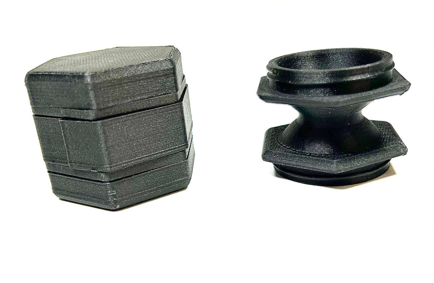
We had enough of a model to create a proof-of-concept prototype of the magnetic concept, which we 3D printed and assembled in house. We all liked this prototype a lot, the magnets
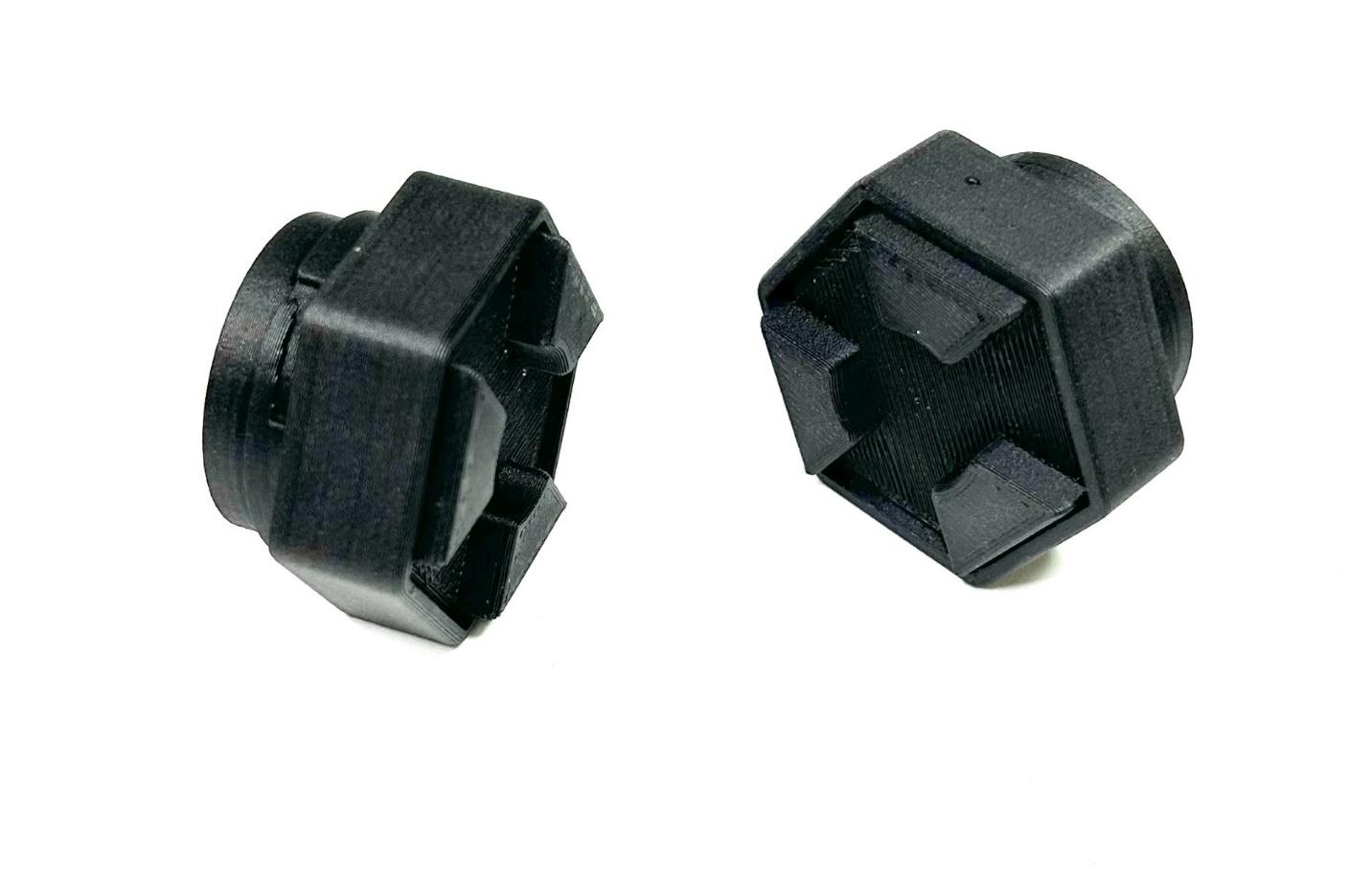
added a cool touch to the design and the user experience of separating and reattaching the halves was satisfying.
However, there were drawbacks too. This was a contact lens case designed for travelers, it needed to be strong enough to stay together when jostled in bags and purses, but weak enough to separate easily when intended. Magnetic parts can also attract metal or other magnetized objects that might cause the case to become dirty with magnetic debris. Outside of mechanical and user experience concerns, there were patentability concerns that ultimately lead us to pivot to a design that didn’t involve magnets.
Pivots in design can be costly, but significantly less costly when made in the conceptual or prototyping phase of a design before design drawings have been made or tooling has been cut. They can also lead to more elegant or useful designs that help elevate your product or avoid major issues later down the road.
We explored a few other concepts for attaching the halves to the point of proof-of-concept prototypes that ultimately weren’t chosen for one reason or the other. Like the magnet concept, some concepts that work well mechanically or look good on a computer screen, have major drawbacks for the end user that become more apparent when a physical prototype is in hand.
Ultimately, we knew we wanted the separation and attachment to be a satisfying experience that left users with a feeling of security but wouldn’t wear or get dirty easily. This iterative prototyping cycle led us to use three metal ball-nose spring plungers to secure the two halves together.
Once that design was proven in a proof-of-concept level prototype and tested by Christine and an internal user group, we moved on to iterative prototyping improvements of just that feature. This involved testing several different sizes of spring plungers, different shapes of the pocket that they fit into to secure the halves to each other, the distances of the plastic parts needed to

make the right clicking sound and finding the goldilocks configuration to make the connection feel secure but still easy to separate when desired
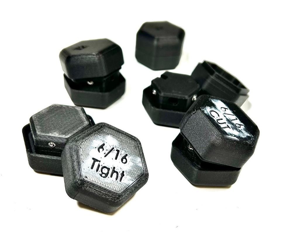
Similarly, the thread connection of the lids to the cavity bodies needed many prototype revisions to get right. Changes to one feature would affect another and needed to be thought through and recalculated. Major time was spent tweaking the CAD model to make incremental improvements and physical 3D printed prototypes were used to check those changes. To test the seal, multiple O-ring sizes and durometers (or hardness levels) were tested, and more expensive waterproof 3D prints had to be ordered
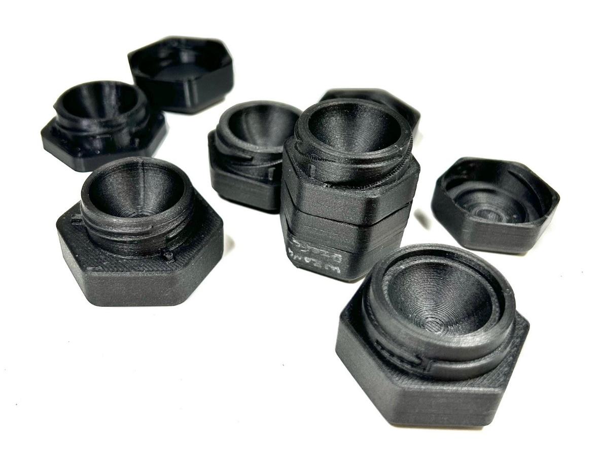
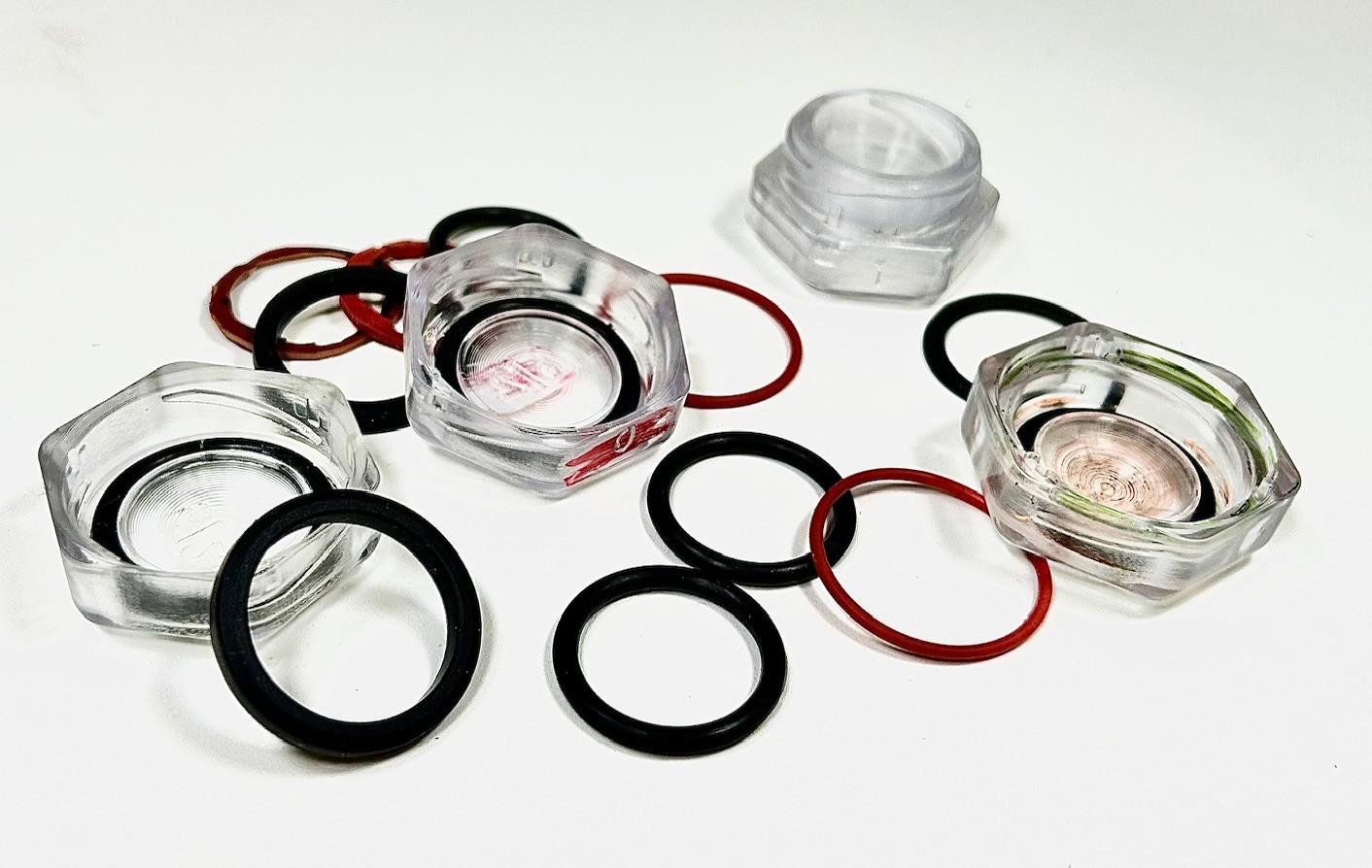
Many of the physical changes were to improve the user experience of the product, which ultimately is a subjective experience that needs feedback from the target audience of the product. It’s not always clear which decision is right as that target market can be split on what they prefer. This is a time period where a product owner needs to make a lot of decisions that will affect the overall look and feel of their product. Decision fatigue can set in as you’re tasked with deciding what click is preferred, how tight it too tight, how much gap should be allowed between parts, etc. We provide our recommendation as product development engineers at most of these steps, but ultimately it’s the product owner, Christine in this case, who makes the final decisions.
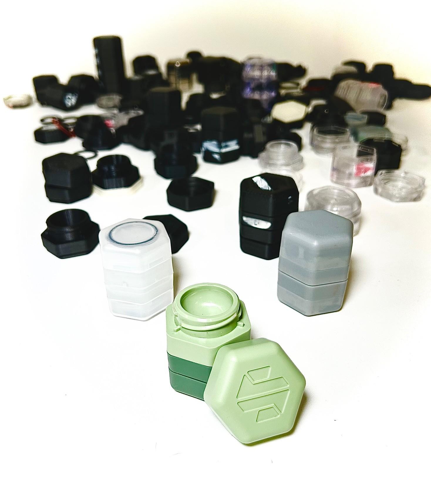
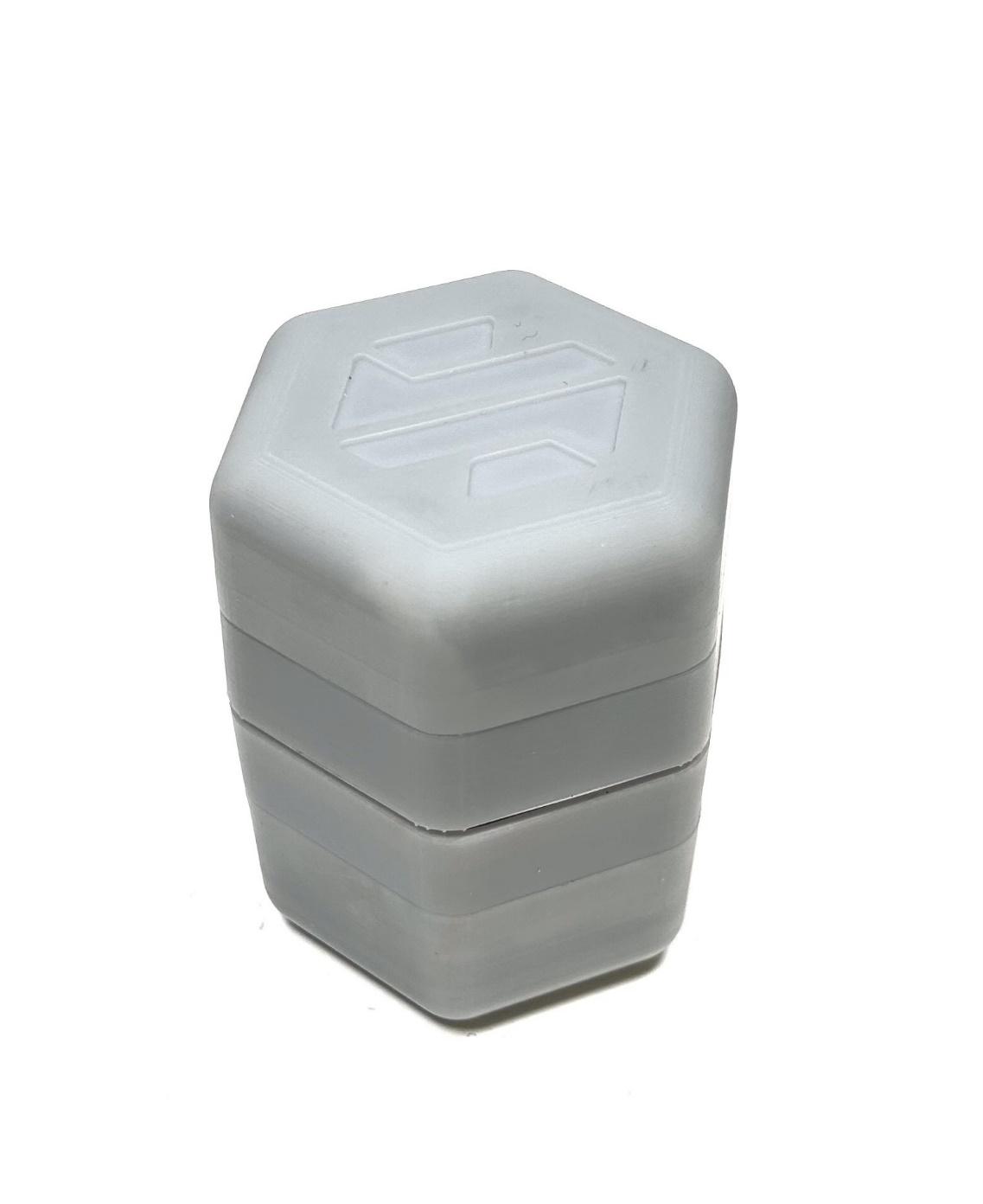
At the end of this phase, a pre-production prototype is produced that is fully functional and looks very similar to the final product. In some cases, this can be hard to do as some mass-production manufacturing methods can be hard to replicate as one-off endeavors. For this product, the injection molded polypropylene plastic for final production was mimicked with SLA 3D printed parts and assembled by hand with superglue and press-fit hardware.
Phase 4: Detailed Design
With the prototype and 3D CAD model created, we could begin engaging manufacturers and creating the design package used to quote tooling and unit pricing and act as a blueprint for how a product is made.
Design for Manufacturing (DFM) is a process of optimizing the design for the process that will be used to produce the part. From the beginning, we knew the main parts of the final product would be injection molded plastic. Injection molding is a process where a mold of your part is created out of steel or aluminum and injected with melted plastic. That part is then cooled and released from the mold with ejectors. The parts need to be designed for both the tooling process of creating the mold and for the injection process of releasing the parts. Throughout concepting, engineering design, and prototyping the constraints for this complex process guided us, but in this stage of DFM, we went even further into the fine details to make sure the parts could be produced. This is a time-consuming process that involves looking at the fillets and chamfers on the parts to ensure molds could be milled with standard bits, making sure adequate draft (or taper angle) was added to all parts so they could be released from the molds, and uniform wall thickness was maintained so that the molten plastic didn’t pool or cause abnormalities in the part, among other details.
In addition to designing for the general manufacturing process, individual manufacturers have their own design requirements and available tooling that must be accounted for. DFM is also a negotiation between designer and manufacturer for how willing the designer is to alter their part design and how willing the manufacturer is to alter their processes to produce the part.
We had started the search for the right manufacturer earlier in the process, as the FDA required parts be produced in a clean room which eliminated many injection molding facilities. We had designed the product to be under a set cost-of-goods sold (COGS) target, or the direct costs of manufacturing a physical product, which narrowed our design and the factories that could produce it. This product would be manufactured and assembled overseas, which added further considerations for manufacturing like finding ethical factories, a broker we could trust, and intellectual property protection. With those details in mind, we went with a production group we already had a relationship with that could be trusted to manage the supply chain and work with manufacturers to create the injection molding tooling, produce the parts, and then assembly, package, and ship out the final product.
While many manufacturers now create tooling from 3D CAD files, a 2D design package is still needed to ensure the part is produced to agreed upon standards and assembled correctly. In this case, we created part drawings for the plastic parts and assembly drawings for the final product. Part drawings call out dimensions with tolerances, for example a drawing might have a length called out as 11.05 +/- 0.025mm. If the manufacturer signs off on that drawing, they are saying every part produced will be a length between 11.025mm and 11.075mm. This range is determined by how accurate their machines can make the molds and also by a fluctuation in the thickness of the plastic due to the heating/cooling process of injection molding.
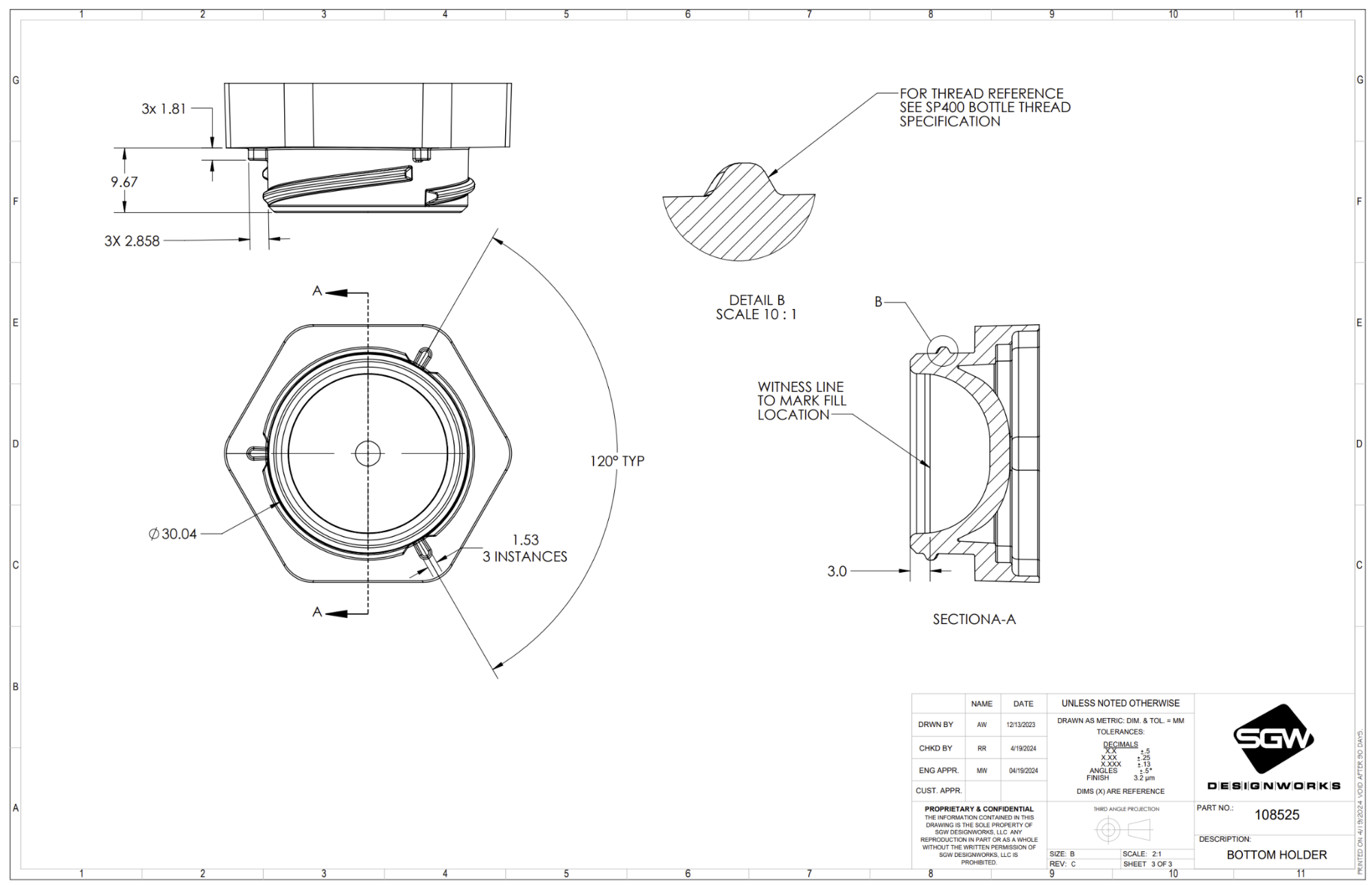
Because every dimension on each part has a tolerance range and an assembly involves combining these individual parts, an important step in DFM for the designer is to calculate the stack up of tolerances throughout the assembly of parts to ensure that the parts will still fit together and function appropriately even if they are slightly different dimensions within that range. In some designs, this is impossible, and designers go into manufacturing knowing there is a risk that a certain percentage of produced parts will not fit properly and will be wasted. In other designs the tolerance range can be fairly loose, as their design doesn’t require a tight fit. Generally, the smaller the tolerance the more expensive the part is to produce as it requires more precise machines to produce the part. For manufacturers, they must also closely monitor the engineering drawings to ensure they can hit the tolerance ranges shown, as any part that falls out of the tolerance range they agreed to will need to be reproduced at their expense.
As we created the 2D design package and negotiated with our manufacturer on tolerances and design changes, we needed to create additional 3D printed prototypes to check that the changes made to one part didn’t adversely affect other parts in the assembly or the user experience overall. This process can happen quickly or take months of back and forth depending on design complexity and capabilities of the manufacturer. It can also be complicated by language barriers, time zones, and supply chain changes. We’ve found that working with manufacturers you trust and have a relationship with from previous projects streamlines the DFM process.
Generally, manufacturers can provide a tooling and unit price estimate prior to in-depth DFM feedback. As the back and forth with designer and manufacturer moves toward an agreed upon design and manufacturing plan, this pricing also solidifies along with a manufacturing timeline and a purchasing order is finalized.
Phase 5: Production Support
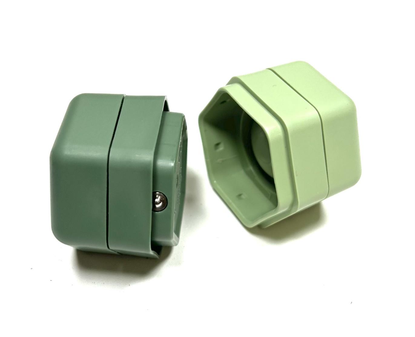
Christine signed a purchasing order for the tooling which began production. For injection molded parts, it’s common to get three sets of samples before going to mass production. The first, called T0 articles (or trial 0), are non-colored, non-textured versions of the parts fully assembled. When the designer receives the parts, they check them against the drawings to make sure the parts and assembly are within the specifications they provided and that there are no obvious deformations or defects. In our case, we also completed leak tests at different pressures to ensure the plastic parts would hold a seal at different altitudes

We then sent our list of corrections to the molder, they made the necessary changes to their molds and produced the next set of samples, T1 articles, which are also non-colored and non-textured. These parts met all our requirements, but if we had further corrections, this process would continue with T2, T3, etc. until all parties were happy with the product. After getting the go ahead, the manufacturer then adds texture to the mold and produces a small run with the final color. This run is called a golden sample and is also sent back to the designer. This is the last chance to make any changes before going to final production. Every manufacturer is different, but generally a down payment is paid when the first purchasing agreement is signed to produce tooling and the rest is paid after approval of the golden sample or upon delivery. Generally, the sampling and correction process takes 2-4 months.
In a similar fashion, we had designed simple packaging for the contact lens case that also had T0, T1, and golden samples that needed to be evaluated and corrected. After approval of the golden samples, Christine requested a small run to be produced for FDA testing, which in her case takes 8-12 weeks to complete. Pending results from testing, her first order should be going to production in the fall.
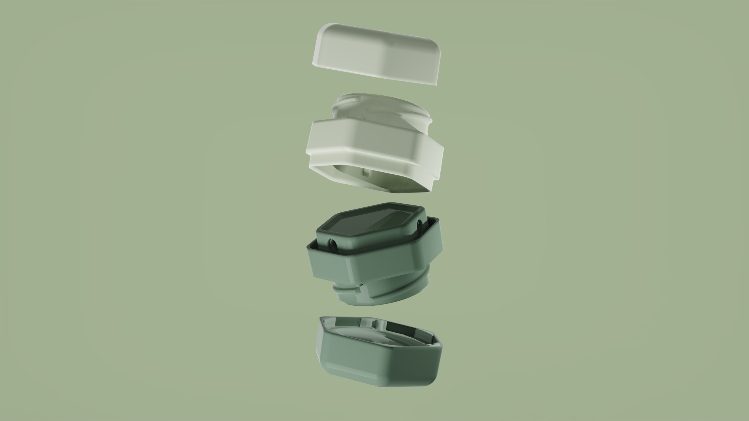
Every product has a different path to development, but they all generally go through these same stages of design: defining the product, concept generation and development, detailed design, prototype development, and manufacturing. While different product development companies may approach this cycle differently, successful product design hinges on following a process to get from idea to production. Christine’s journey through these stages of product development shows just one example of this process, but it’s one that we’ve found to be highly successful from first-time product inventors to industrial giants.
Have questions? Get in touch with a product development engineer at SGW Designworks at info@sgwdesignworks.com.

.jpg)
